Frame是布局的核心。每个开发者都使用frame定位和改变UIView和CALayer的大小。在本文中我将把焦点集中在CALayer上,因为它是UIView的底层实现,view.frame简单的返回了view.layer.frame。
Frame是布局的核心。每个开发者都使用frame定位和改变UIView和CALayer的大小。在本文中我将把焦点集中在CALayer上,因为它是UIView的底层实现,view.frame简单的返回了view.layer.frame。此外,我不会讨论setFrame:方法。虽然看起来范围十分有限,但实际上有许多有趣的事情在平凡又古老的frame getter方法中发生。
Frame依赖于什么
众所周知,frame是一个派生属性,实际上它基于一些其他的属性。实际上在计算frame值的时候会参考4个(!)属性:bounds、anchorPoint、transform、position。
bounds
bounds很棘手,它混合了层的内部和外部。bounds.size定义了层本身的面积,声明了它所存在的区域。设置masksToBounds为YES会把所有子层超出bounds范围的部分裁掉。另一方面,bounds的origin属性并不影响层本身的布局。然而它会影响它内部的子层的布局方式。bounds.origin定义了层内部坐标系的原点。
案例1
这里有一个例子展示了bounds.origin如何工作。例如我们定义bounds.origin为CGPointMake(20.0f, 30.0f)
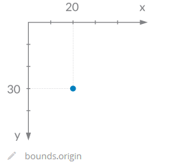
如何定义本地坐标系?只要把层的左上角放到bounds.origin上就行了。
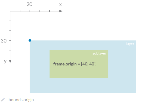
案例2
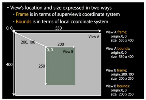
- frame: 该view在父view坐标系统中的位置和大小。(参照点是,父亲的坐标系统)
- bounds: 该view在本地坐标系统中的位置和大小。(参照点是,本地坐标系统,就相当于ViewB自己的坐标系统,以0,0点为起点)。
其实本地坐标系统的关键就是要知道的它的原点(0,0)在父坐标系统中的什么位置(这个位置是相对于父view的本地坐标系统而言的,最终的父view就是UIWindow,它的本地坐标系统原点就是屏幕的左上角了)。
通过修改view的bounds属性可以修改本地坐标系统的原点位置。
frame我相信大家都理解的比较清楚,但是bounds光是这么说估计大家都很迷糊,那么我们下面来看具体的实例。
bounds到底起什么作用
示例代码
1 | UIView *view1 = [[UIView alloc] initWithFrame:CGRectMake(100, 100, 200, 200)]; |
效果图
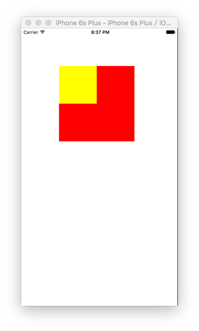
输出日志
1 | view1 frame:{{100, 100}, {200, 200}}========view1 bounds:{{0, 0}, {200, 200}} |
下面我们来改变view1的bounds,代码如下
1 | [view1 setBounds:CGRectMake(-20, -20, 200, 200)]; |
此时显示和输出日志如下所示:
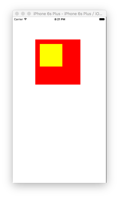
1 | view1 frame:{{100, 100}, {200, 200}}========view1 bounds:{{-20, -20}, {200, 200}} |
分析
上面设置view1的bounds的代码起到了让view2的位置改变的作用。为何(-20,-20)的偏移量,却可以让view2向右下角移动呢?
这是因为setBounds的作用是:强制将自己(view1)本地坐标系的原点改为(-20,-20)。这个(-20,-20)是相对view1的父view(self.view)偏移的。也就是向左上角偏移。
那么在view1的坐标系中(0,0)这个点是需要向右下各偏移20。
因为view1的subview(view2)的frame参照的坐标系是父view(view1)的bounds设置的,而此时view2的frame设置为(0,0),就会导致view2向右下各偏移20。如上图所示。
总结:
所以,bounds的有这么一个特点:
它是参考自己坐标系,它可以修改自己坐标系的原点位置,进而影响到子view的显示位置。
bounds使用场景
其实bounds我们一直在使用,就是我们使用scrollview的时候。
为什么我们滚动scrollview可以看到超出显示屏的内容。就是因为scrollview在不断改变自己的bounds,从而改变scrollview上的子view的frame,让他们的frame始终在最顶级view(window)的frame内部,这样我们就可以始终看到内容了。
下面通过一个具体的例子来看看:
1 | self.imageview = [[UIImageView alloc]initWithFrame:CGRectMake(100,0, 50, 1000)]; |
在向上滚动过程中,输出scrollview的frame,bouns,contentoffset和子控件imageview的frame,bounds
1 | -(void)scrollViewDidScroll:(UIScrollView *)scrollView{ |
输出结果如下

分析
可以看到imageview的frame和bounds还有scrollview的frame是没有改变的。唯一在不断改变的是scrollview的contentoffset和bounds,而且两者完全相同。
结合上面我们讲的知识,就不难理解为什么scrollview要这么做了。
向上滚动scrollview,我们就不断增加scrollview的bounds的y值,也就是不断把scrollview的本地坐标系原点向下偏移(相对于scrollview的父view的坐标系,y值越大,越向下偏移)。那么此时scrollview的子控件的frame设置的(0,0)就是不断向上偏移
假设某一时刻scrollview的坐标系原点为(0,100),那么scrollview的(0,0)位置就是相对于坐标系原点向上偏移100的距离,设置scrollview的子控件的frame为(0,0),就是设置子控件左上角在scrollview中的(0,0)位置,那么子控件就会向上偏移100,你也就看到scrollview的内容(子控件)向上滚动的效果。
其实我们可以使用文章开始的例子来模式UIScrollview的滚动效果,经过上面的分析我们知道就是通过不断增加UIScrollview的bounds的Y值,才可以出现滚动效果从而显示超出屏幕的内容。
那么使用文章开头的例子,我们可以不断增加view1的bounds的y值,来看看是不是可以达到同样的效果:view1不动,view2在不断向上滚动
1 | UIView *view1 = [[UIView alloc] initWithFrame:CGRectMake(100, 200, 200, 100)]; |
运行看看,可以发现view1固定不动,view2在不断向上滚动,此时的view1就相当于UIScrollview,而view2相当于UIScrollview上面显示的内容,现在明白了吗?
bouns大于frame的情况
假设设置了控件的bounds大于frame,那么此时会导致frame被撑大,frame的x,y,width,height都会改变。

结论
- 新的frame的size等于bound的size。
- 新的frame.x = 旧frame.x - (bounds.size.witdh - 旧frame.size.width)/2
- 新的frame.y = 旧frame.y - (bounds.size.height - 旧frame.size.height)/2
bound的改变会累加
假设view1上面添加了view2,view2上面添加了view3。三个view的size都是(100,100)。
我们设置如下:
view1.bound = (0,100,100,100)
view2.bound = (0,100,100,100)
那么此时view3.frame = (0,0,100,100),view3会相对于原来没有设置view1、view2的bound时的位置向上偏移200。
总结:
frame是参考父view的坐标系来设置自己左上角的位置。
设置bounds可以修改自己坐标系的原点位置,进而影响到其子view的显示位置。
anchorPoint
之前提到过,视图的center属性和图层的position属性都指定了anchorPoint相对于父图层的位置。图层的anchorPoint通过position来控制它的frame的位置,你可以认为anchorPoint是用来移动图层的把柄。
默认来说,anchorPoint位于图层的中点,所以图层的将会以这个点为中心放置。anchorPoint属性并没有被UIView接口暴露出来,这也是视图的position属性被叫做center的原因。但是图层的anchorPoint可以被移动,比如你可以把它置于图层frame的左上角,于是图层的内容将会向右下角的position方向移动(图3.3),而不是居中了。
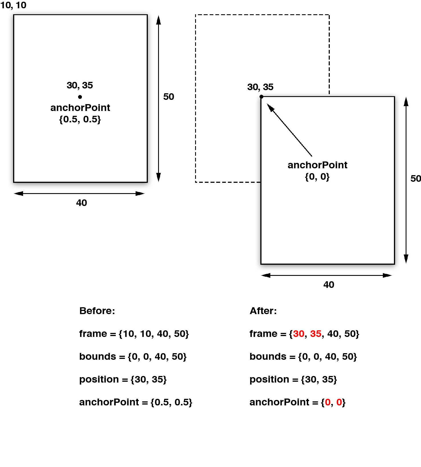
图3.3 改变anchorPoint的效果
和第二章提到的contentsRect和contentsCenter属性类似,anchorPoint用单位坐标来描述,也就是图层的相对坐标,图层左上角是{0,0},右下角是{1,1},因此默认坐标是{0.5, 0.5}。anchorPoint可以通过指定x和y值小于0或者大于1,使它放置在图层范围之外。
注意在图3.3中,当改变了anchorPoint,position属性保持固定的值并没有发生改变,但是frame却移动了。
那在什么场合需要改变anchorPoint呢?既然我们可以随意改变图层位置,那改变anchorPoint不会造成困惑么?为了举例说明,我们来举一个实用的例子,创建一个模拟闹钟的项目。
钟面和钟表由四张图片组成(图3.4,为了简单说明,我们还是用传统的方式来装载和加载图片,使用四个UIImageView实例(当然你也可以用正常的视图,设置他们图层的contents图片)。
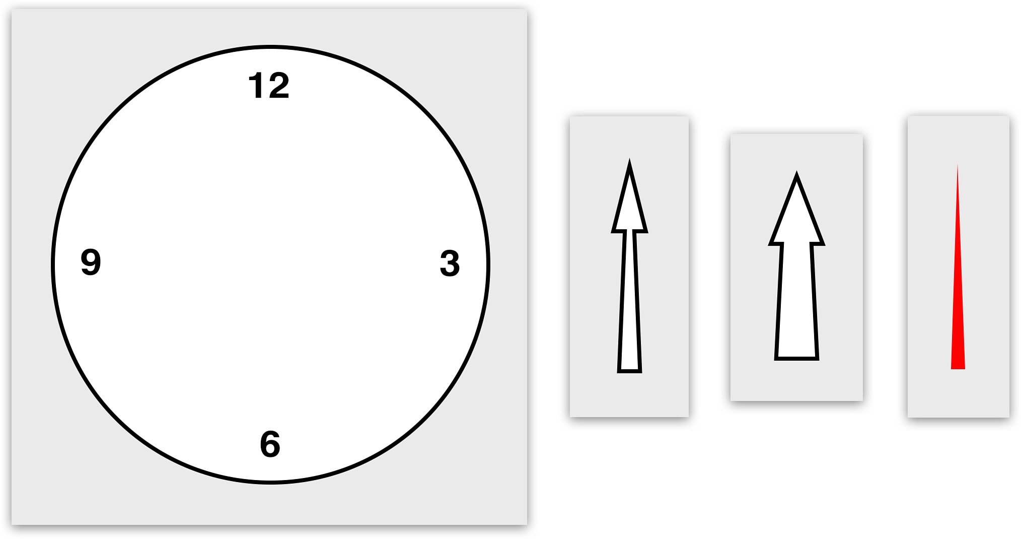
图3.4 组成钟面和钟表的四张图片
闹钟的组件通过IB来排列(图3.5),这些图片视图嵌套在一个容器视图之内,并且自动调整和自动布局都被禁用了。这是因为自动调整会影响到视图的frame,而根据图3.2的演示,当视图旋转的时候,frame是会发生改变的,这将会导致一些布局上的失灵。
我们用NSTimer来更新闹钟,使用视图的transform属性来旋转钟表(如果你对这个属性不太熟悉,不要着急,我们将会在第5章“变换”当中详细说明),具体代码见清单3.1
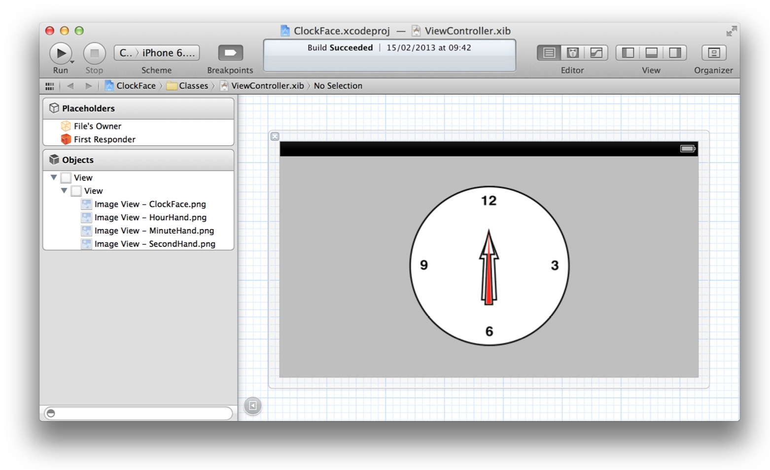
图3.5 在Interface Builder中布局闹钟视图
清单3.1 Clock
1 | @interface ViewController () |
运行项目,看起来有点奇怪(图3.6),因为钟表的图片在围绕着中心旋转,这并不是我们期待的一个支点。
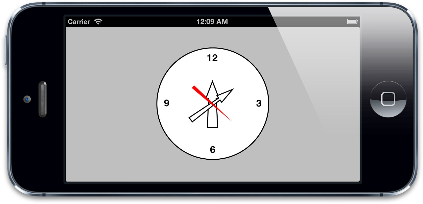
图3.6 钟面,和不对齐的钟指针
你也许会认为可以在Interface Builder当中调整指针图片的位置来解决,但其实并不能达到目的,因为如果不放在钟面中间的话,同样不能正确的旋转。
也许在图片末尾添加一个透明空间也是个解决方案,但这样会让图片变大,也会消耗更多的内存,这样并不优雅。
更好的方案是使用anchorPoint属性,我们来在-viewDidLoad方法中添加几行代码来给每个钟指针的anchorPoint做一些平移(清单3.2),图3.7显示了正确的结果。
清单3.2
1 | - (void)viewDidLoad |
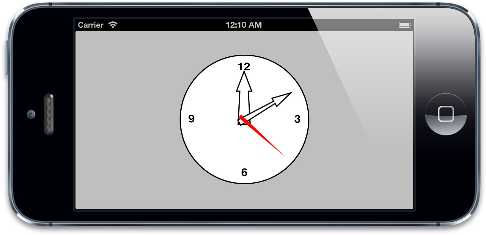
图3.7 钟面,和正确对齐的钟指针
transform
在一些极端情况下,使用float和double的差异是显而易见的。然而因为我们的目标是对CoreAnimation进行逆向工程并得到完全相同的结果,所以我们也使用double。我们定义一些和CoreGraphics中相同的非常简单的结构体。
1 | typedef struct MCSDoublePoint { |
值得注意的是在64位iOS设备上,我们精心构建的struct会变得多余,因为在该架构上,CGPoint,CGSize和CGRect本来就是用doubles的。
虽然CALayer使用的是一个完整的4×4的矩阵模拟CATransform3D,但它对计算frame的目的真的没有影响。所以,我们把焦点集中在CGAffineTransform上,它可以用每个人都喜欢的CATransform3DGetAffineTransform方法从CATransform3D中简单获得。
让我们从点开始,使用仿射变换来变换点是入门级的袋鼠:
1 | MCSDoublePoint MCSDoublePointApplyTransform(MCSDoublePoint point, CGAffineTransform t) |
上面的代码实现基于CGPointApplyAffineTransform,从根本上来讲是一个3x3的变换矩阵乘一个三维向量。

这个矩阵被CGAffineTransform的值填充,被乘的向量由点的x坐标,y坐标和1.0组成,让结果向量从矩阵中也得到转换过的元素。
通过点变换,我们很容易变换矩形。通过变换矩形的顶点并用直线连接它们创建一个平行四边形(通常可以是任意四边形)。但这并不是CGRectApplyAffineTransform的如何工作的。这个函数接收一个CGRect参数并返回一个CGRect。正如头文件CGAffineTransform.h中的注释声明的:
通常来说因为仿射变换并不保护矩形,这个函数返回一个最小的包括经过变换的rect的四个顶点的矩形。
读过这个以后,使用double再现CGRectApplyAffineTransform变得相对直接:
1 | MCSDoubleRect MCSDoubleRectApplyTransform(MCSDoubleRect rect, CGAffineTransform transform) |
我们计算了四个顶点的坐标,变换它们并且得到x和y的极值。
计算Frame
我们付出努力去理解我们关心的每一件事,现在,获得frame会是很热闹:
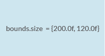
定义一个面积为bounds.size的矩形
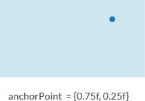
计算该矩形内的anchorPoint位置
将矩形放入坐标系内,anchorPoint作为坐标系的原点
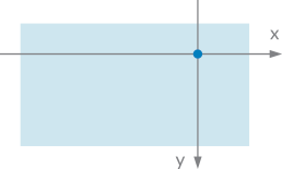
应用任何你实施的变换,保持一个包含了经过转换的顶点的最小矩形
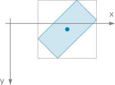
根据position移动anchorPoint
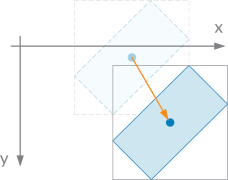
灰色的就是结果矩形
实现这些操作的代码如下:
1 | - (CGRect)frameWithBounds:(CGRect)bounds anchorPoint:(CGPoint)anchorPoint transform:(CATransform3D)transform position:(CGPoint)position |
position
在layer体系结构中,layer需要添加在supLayer中,才可以显示出来(和view体系结构相似)。因此,每一个显示出来的layer都有一个supLayer。
position是layer中的anchorPoint点在superLayer中的位置坐标.
anchorPoint、position、frame之间的相对关系
首先弄清楚这三个属性表示什么. 回顾一下上面讲的.
- frame中的X,Y表示sublayer左上角相对于supLayer的左上角的距离
- position中的X,Y表示sublay锚点相对于supLayer的左上角的距离
- anchorPoint中的X,Y表示锚点的x,y的相对距离比例值
当确定锚点,改变frame时, position的值为:
1 | position.x = frame.origin.x + anchorPoint.x * bounds.size.width |
确定锚点,改变position时,frame的值为:
1 | frame.origin.x = position.x - anchorPoint.x * bounds.size.width |
改变锚点,frame的值变化为:
1 | frame.origin.x = - anchorPoint.x * bounds.size.width + position.x; |
影响关系:
- 锚点改变,position不影响,frame变化
- frame变化,锚点不影响,position变化
- position变化,锚点不影响,frame变化